Contactor Wiring Diagram A1 A2
The contactor terminals for connection of the motor leads are almost always marked t1, t2, and so on. Low voltage or high voltage applied to the coil.
Contactor Wiring Diagram A1 A2 Sample Wiring Collection

From s2 on the motor connect a cable to directional contactor c.

Contactor wiring diagram a1 a2. The main contacts need to be connected to the three phases of a, b, and c. A1 and a2 are the coil terminals of a contactor. Sport conrad voucher code 2021.
On the front of the contactor, you’ll see two wire terminals of a1 and a2. It's a 2 pole contactor with a1/a2 and 1234 am i right in thinking that a1 = perm live a2= neutral 1= live to light 2= switched live not really sure on 3 and 4 thanks for any advice A wiring diagram is a simplified standard pictorial depiction of an electric circuit.
It should make it a lot easier to wire everything together. The auxiliary contacts of the contactor are connected to the control circuit. Those correspond with the letters on the diagram that came with your contactor.
On abb contactor wiring diagram. From a2 on the motor connect to directional contactor terminal a. I've not had to do a contactor before and just want to check the wiring of it.
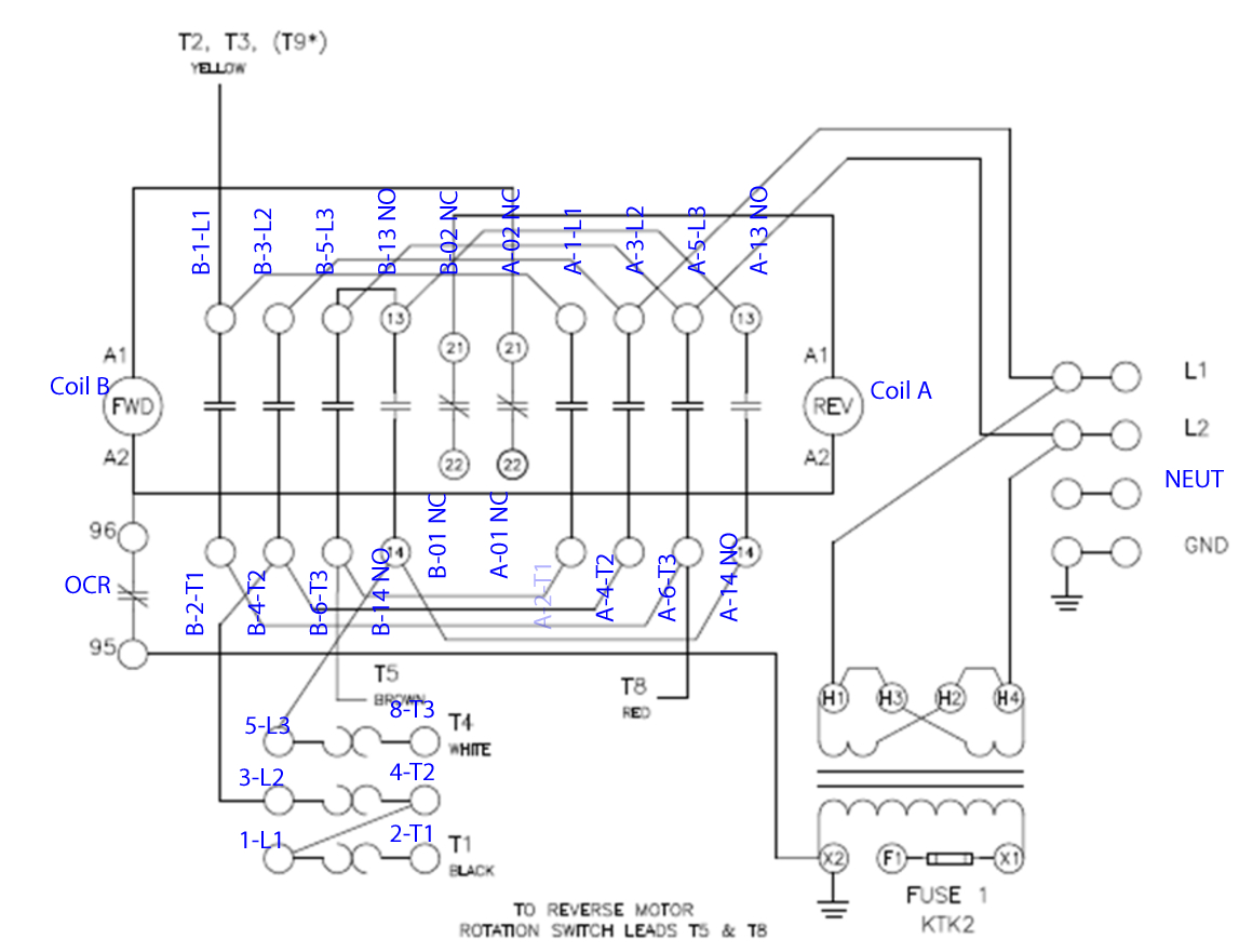
A1 a2 t1 t2 t3 24 6 l1 or disconnect switch l2 l3 circuit breaker stop start m ot* t1 t2 t3 m m solid state overload relay 1ct m m motor 3ct to 120 v separate control * ot is a switch that opens when an overtemperature condition exists (type mfo and mgo only) t1 t3 motor 3 2 l2 t2 l3 t3 t2 l1 1 t1 13 14 43 44 53 54 31 32 21 22 status. Many contactor manufacturers use the designations a1 and a2 for the terminals that connect power to the magnetic coil. A wiring diagram is a simple graph of the physical connections as well as physical format of an electrical system or circuit.
Your switch sends 110v through this to turn the contactor on (closed) and off (open). Usually the electrical wiring diagram of any hvac equipment can be acquired from the manufacturer of this equipment who provides the electrical wiring diagram in the users manual see fig1 or sometimes on the. The touch or starting current goes from the reverse push and hook up with the primary contactor normally close auxiliary contact/terminal and from the.
On the opprvlwh terminal connect a red coded cable to b+ on the controller. Contactor wiring diagram a1 a2. Green and red or start and stop buttons.
Each part should be set and connected with other parts in particular way. Overcurrent flowing through the contacts. Essential tips for safe electrical repairs.
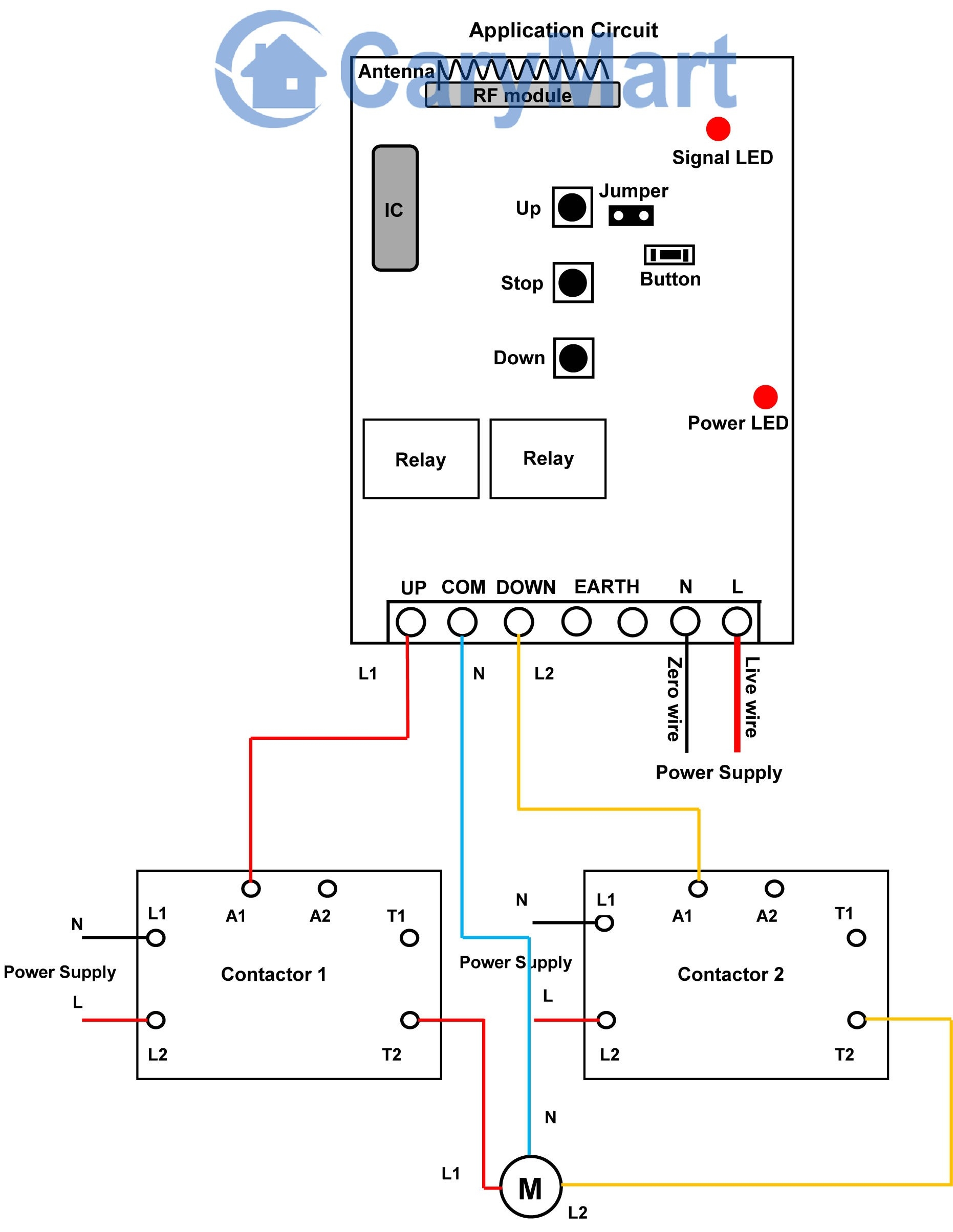
Wiring diagram book a1 15 b1 b2 16 18 b3 a2 b1 b3 15 supply voltage 16 18 l m h 2 levels b2 l1 f u 1 460 v f u 2 l2 l3 gnd h1 h3 h2 h4 f u 3 x1a f u 4 f u 5 x2a r. The coil a1 of the 220v ac contactor should be connected to the phase line 220v (live wire), and the other a2 needs to be connected to the neutral wire. The above diagram is a complete method of single phase motor wiring with circuit breaker and contactor.
Dust, corrosion, or vibration in the environment. Wiring diagram book a1 15 b1 b2 16 18 b3 a2 b1 b3 15 supply voltage 16 18 l m h 2 levels b2 l1 f u 1 460 v f u 2 l2 l3 gnd h1 h3 h2 h4 f u 3 x1a f u 4 f u 5 x2a r power on optional x1 x2115 v. A wiring diagram generally provides info about the family…
What are a1 and a2 on a contactor? 2 pole contactor wiring diagram. Line contactor (leave actual connection to the battery loose for now).
What causes a contactor to fail or get stuck? 2 days ago i wired 380 to 440 volts contactor for a 3 phase motor and save these images of contactor in pc. Electrical connections boundary seal to be in accordance with article 501.
Repairing electrical wiring, more than some other household project is about safety. Most conductors label the terminals with letters like l, n, e, a1, a2, l, and p. Unique wiring diagram of lg window ac diagram.
From b+ on the controller connect a cable to a1 on the motor. Contactors are used to provide this isolation. Contactor wiring diagram a1 a2 effectively read a cabling diagram, one provides to learn how the particular components within the method operate.
80020 typical wiring diagrams for push button. It reveals the parts of the circuit as simplified shapes, and also the power and also signal connections between the devices. Variety of contactor wiring diagram a1 a2.
A1 is positive, a2 is the negative terminal. For instance , if a module is powered up and it also sends out a new signal of fifty percent the voltage and the technician does not know this, he would think he has a challenge, as this individual would expect the 12v signal.
Single Phase Contactor Wiring Diagram A1 A2

Tork Wiring Schematic for Lighting Contactor and Photocell

Contactor Wiring Diagram A1 A2 Collection Wiring Diagram
Single Phase Contactor Wiring Diagram A1 A2

Contactor Wiring Diagram A1 A2 CASSANDRALANDER

Single Phase Contactor Wiring Diagram A1 A2

Contactor Wiring A1 A2 Electrical Wiring
Contactor Wiring Diagram A1 A2 Free Wiring Diagram

Single Phase Contactor Wiring Diagram A1 A2 Wiring Corner
Contactor Wiring A1 A2 Electrical Wiring

I am trying to connect a nc1 chint 240v contractor to

Contactor Wiring Diagram A1 A2 Free Wiring Diagram

Contactor Wiring Diagram A1 A2 Sample Wiring Collection

Contactor Wiring Diagram A1 A2 Tuts Street
Contactor Wiring Diagram A1 A2 Collection Wiring Diagram
Contactor Wiring Diagram A1 A2
Pin on Elektroniikka

Contactor Overload Maintained Switch wiring for Motor
Contactor Wiring Diagram A1 A2 A2 Wiring Diagram Wiring